Products & Services
- • Bus duct products & Services
- • Switchgear Products
- • Disconnect Switch
- • Crown-sulator ®
- • Joule-ious 105
- • Field Services
Bus duct products & Services

• Iso Phase
The following definitions are taken from the ANSI / IEEE Standard for Metal-Enclosed Bus C37.23-2003 and are the applicable definitions underpinning Crown Electric Engineering and Manufacturing LLC's product offering;
Per section 3.10 types of Metal Enclosed bus assemblies: In general, there are three basic types of construction used: Non-segregated phase, Segregated-phase, and Isolated-phase.
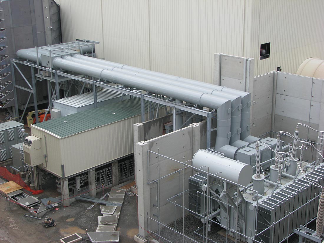
Isolated-phase bus
One in which each phase conductor is enclosed by an individual metal housing separated from the adjacent conductor housing by an air space. The bus may be self-cooled or may be force-cooled by means of circulating a gas or liquid.
Isolated Phase Bus (Non-Continuous and Continuous)
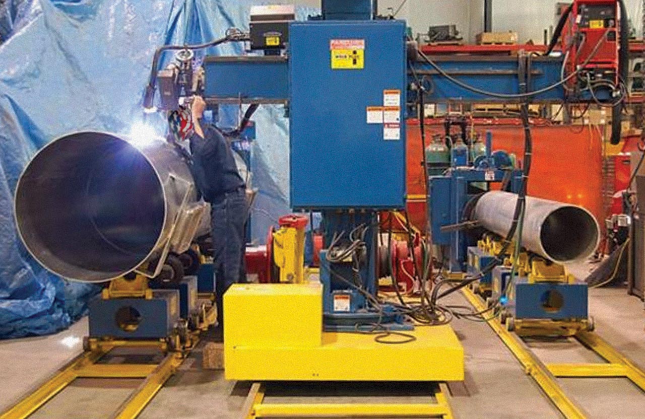
For all new applications, Crown Electric Engineering & Manufacturing LLC engineers, fabricates and offers installation services for Continuous Housing Designs of all Isolated Phase Bus systems.
For legacy projects, Crown Electric supports, maintains, provides fabricated components and upgrades for both Continuous and Non-Continuous Iso Phase designs.
User Benefits Common to both Continuous and Non-Continuous IPB Housing Designs;
Minimal Phase-to-Phase Fault Danger
Two grounded housing walls with an external air space between adjacent phases greatly minimizes the possibility of phase-to-phase and three-phase faults.
Contamination Protection
Conductors and supporting insulator surfaces are well protected from contaminating atmosphere. Potential moisture accumulation within the IPB housing enclosures of the self-cooled design is prevented by installation of outdoor rated filter-type drain plugs. In forced-cooled designs, enclosure moisture accumulates on the heat exchanger coils. This condensation is then drained off.
Personnel Safety
The IPB's grounded enclosures provide electrical isolation from the encased conductor.
Inspection Systems
Legacy insulator mountings were historically designed to permit maintenance access for inspection and cleaning of the entire insulator surface and inspection and tightening of the supporting hardware. Locations where bolted joints exist were designed in such a way as to provide access for inspection and tightening. Crown can additionally incorporate inspection windows and other additional access points as may be specified and desired.
Benefits Offered by Continuous Housing Design
Flux Shielding
All but a small percentage of the total flux is contained within the housing, virtually eliminating induced heating in nearby metal such as IPB enclosures and structural supports.
Reduced Installation Time
By supplying IPB in the greatest practical lengths, field installation time is greatly reduced. The lighter weight of aluminum IPB simplifies structural steel designs permitting easier handling and safer, quicker installation.
Entire Housing at Same Potential
Continuous housing designs eliminate electrically isolated sections associated with non-continuous designs. There are no voltage potential differences between housing sections.
Elimination and Control of Forces
Centering the conductor inside the IPB housing balances the interaction of the continuous concentric magnetic fields of the conductor and the housing. This further eliminates transverse short circuit forces on the support insulators as well as external magnetic fields.
Self Supporting
Continuous IPB requires no special supporting framework as previously required by older non-continuous designs. Simple hangers or floor supports can easily carry the weight of long IPB spans.
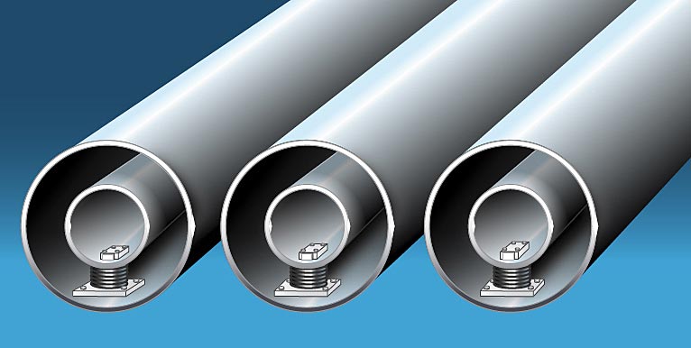
Insulator Support
Crown's proven mechanical-electrical Insul-MountTM insulator support design results in the fewest required insulators per linear span, which corresponds to a direct reduction in the number of potential failure points and creepage paths to ground.
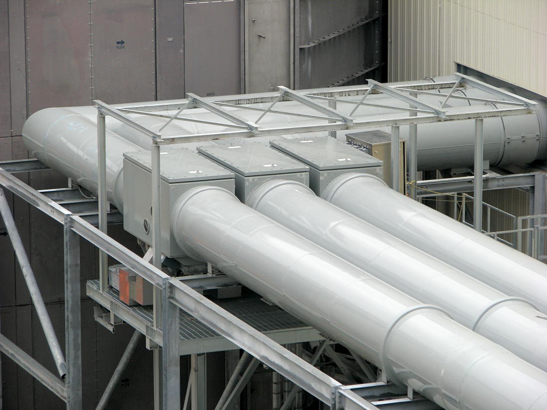
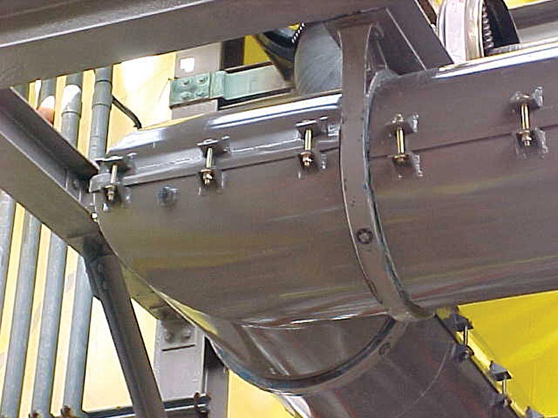
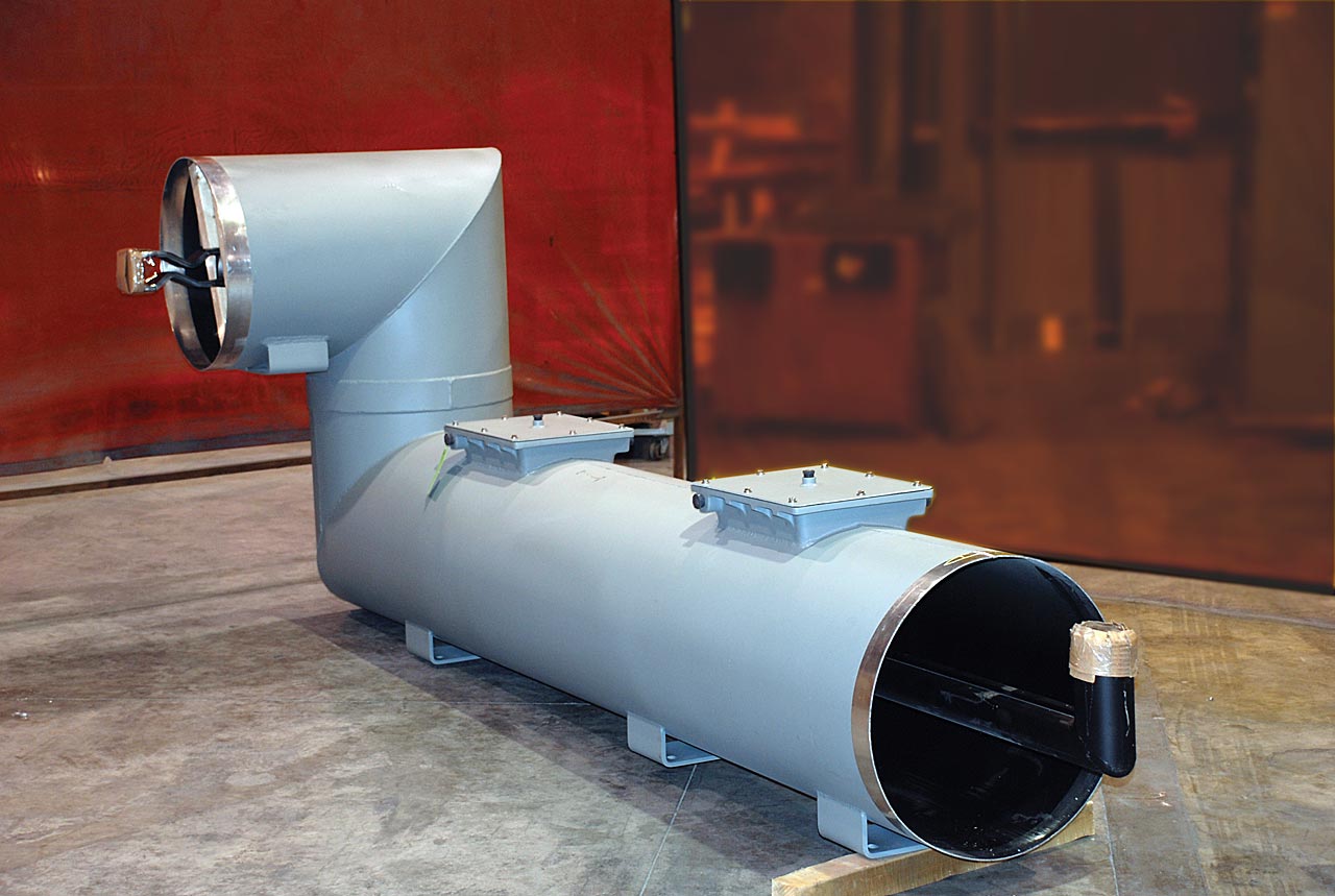
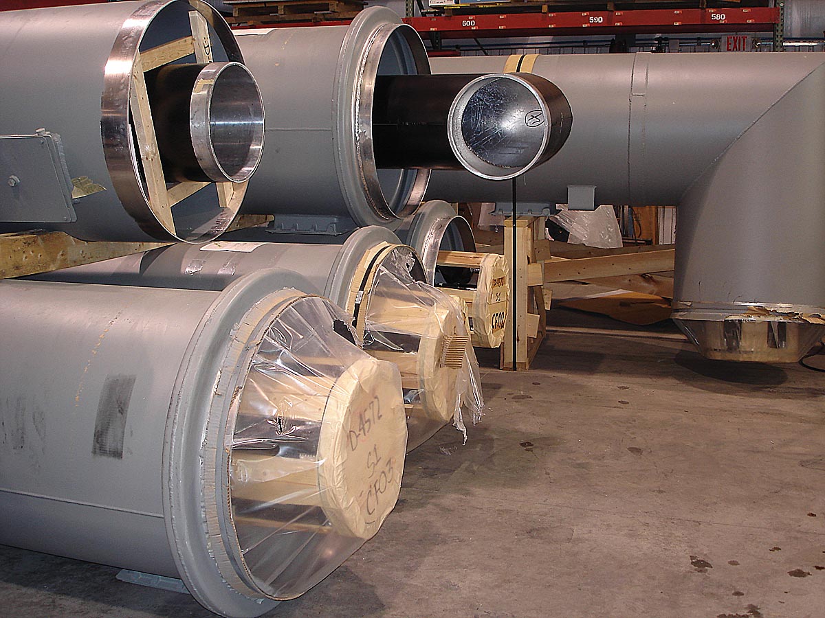
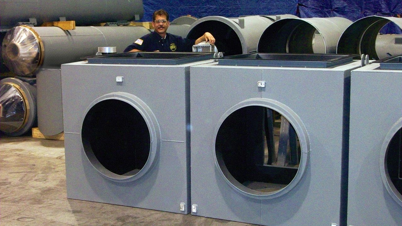
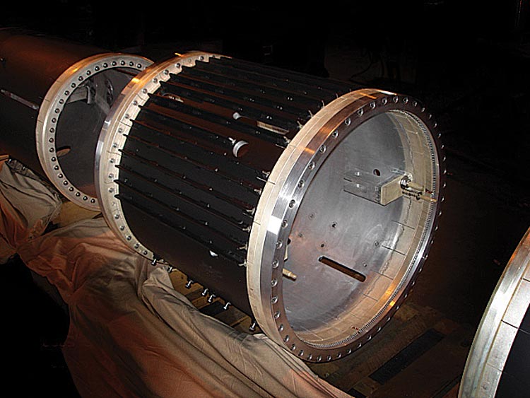
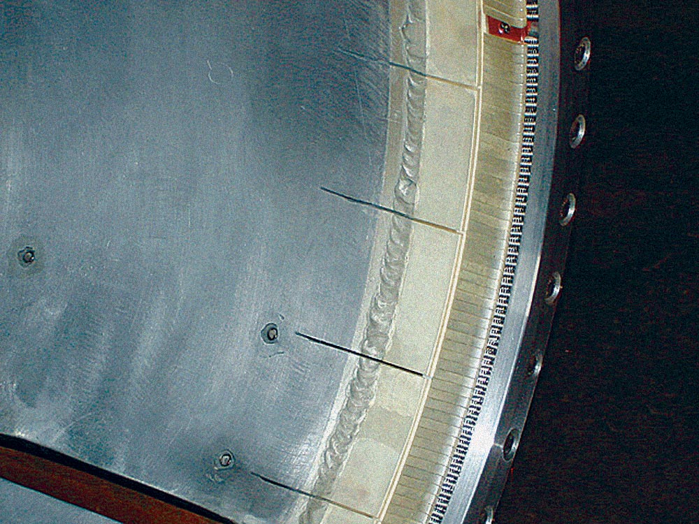
General description of the Continuous Housing design:
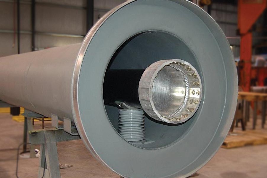
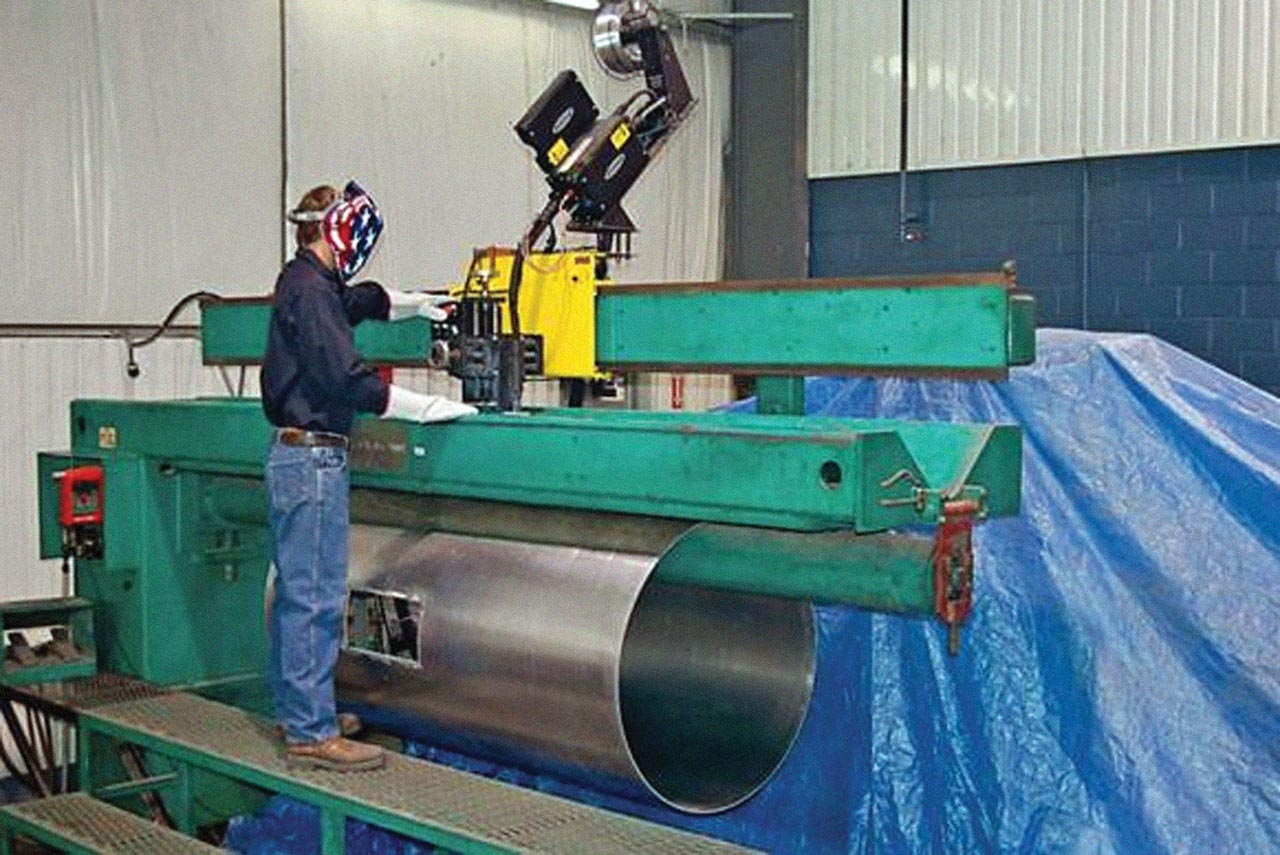
Continuous housings are fabricated from lightweight aluminum sheet rolled and then seam welded to the appropriate diameter for each rating. Cylindrical sections are joined by perimeter welding for maximum strength and conductivity, creating an effective weather tight seal. The cylinder's diameter and material thickness will vary with the system ampacity and BIL rating, but is always of sufficient strength to provide rigidity over the entire IPB span.
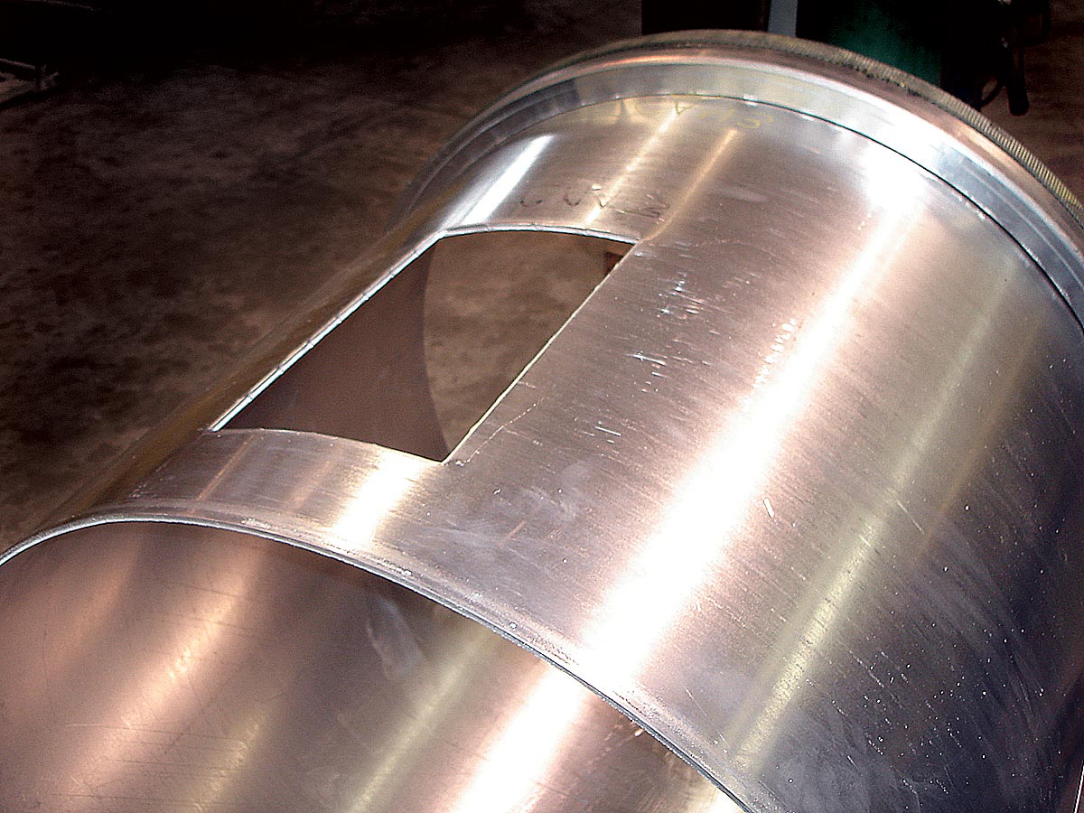
Rectangular openings are placed along the IPB run at appropriate intervals.
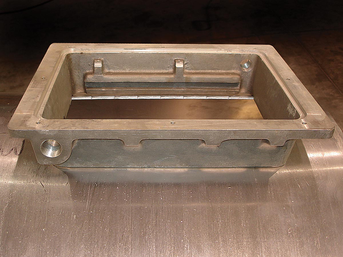
Crown custom designed Insul-Mounttm insulator mounting castings are welded to the enclosure at these longitudinal openings and become the location and foundation of the insulator support system. These openings are designed to provide access for internal inspection of the insulator, mounting hardware and the local internal IPB.
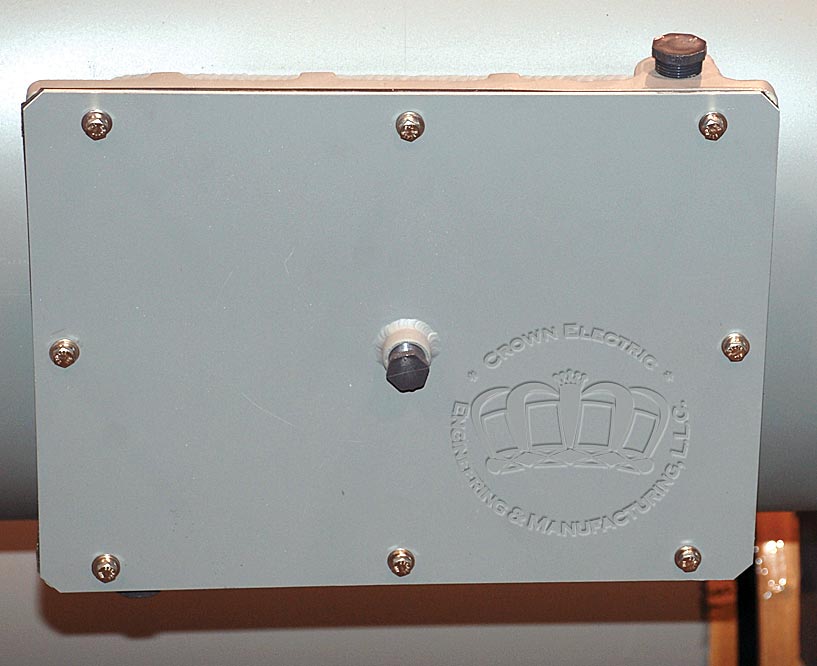
The conductor support insulators may be inspected and cleaned by removing the Insul-Mounttm bolted cover base plate.
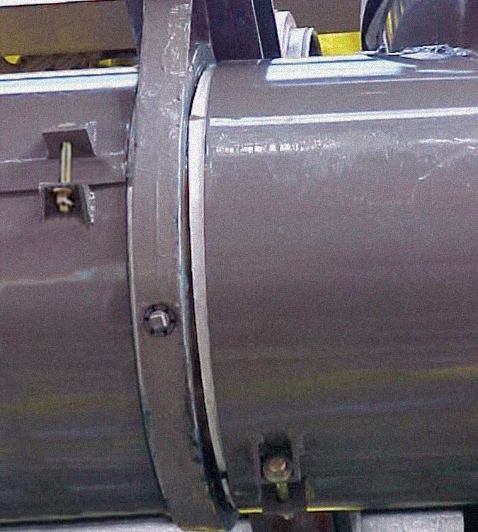
Expansion joints are inserted in the conductor and the enclosure as required.
Vibration joints are provided as specified at the IPB ring termination's of the generator, transformers and breakers.
Mounting saddles are welded to the enclosure at appropriate intervals. These saddles are then secured to the structural steel framework. The IPB's rigidly welded housings contribute to the overall system's mechanical and structural integrity assuring strength while minimizing weight and optimizing material usage.
Taking advantage of the inherent structural strength of the continuous housing design; fewer support points are required, longer lengths can be fabricated and shipped and a simpler structural support system can be employed. Predominantly of welded construction, the continuous housing design reduces the ingress of dust, moisture and foreign contaminants. Aluminum housings are inherently corrosion-resistant, lighter in weight and easier to handle. The continuous housing design simplifies installation and reduces construction time by keeping joints to a minimum.
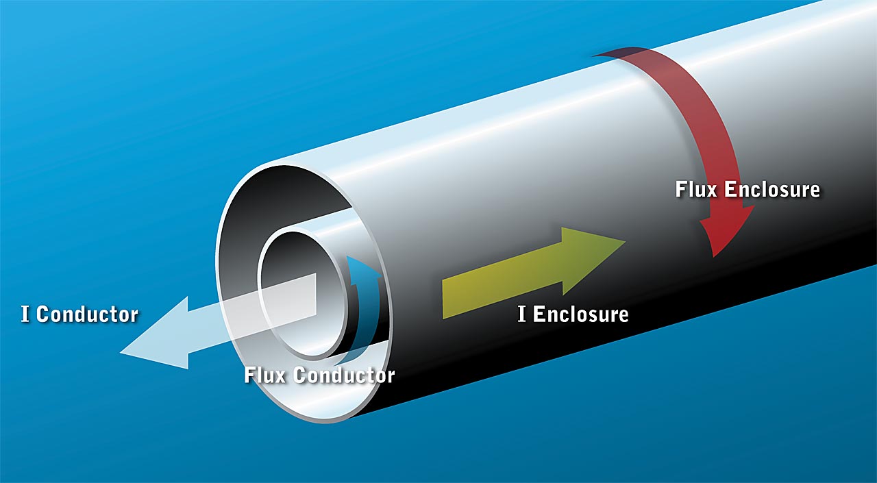
It is possible to think of the joined system created by the interaction of the IPB's conductor and enclosure as an air core transformer with a 1:1 turns ratio producing near equal and opposite currents flowing in each. Therefore, for all practical purposes, continuous IPB designs have no external magnetic flux as the magnetic flux created by the equal and opposite currents flowing in the conductor and enclosure counter balance each other. This flux mitigation results in virtually no heating of adjacent structural supports, conduits, piping or concrete rebar. Just as important; there is no need to contend with stray voltages being induced in sensitive instrument or control circuits.
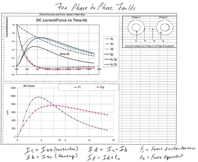
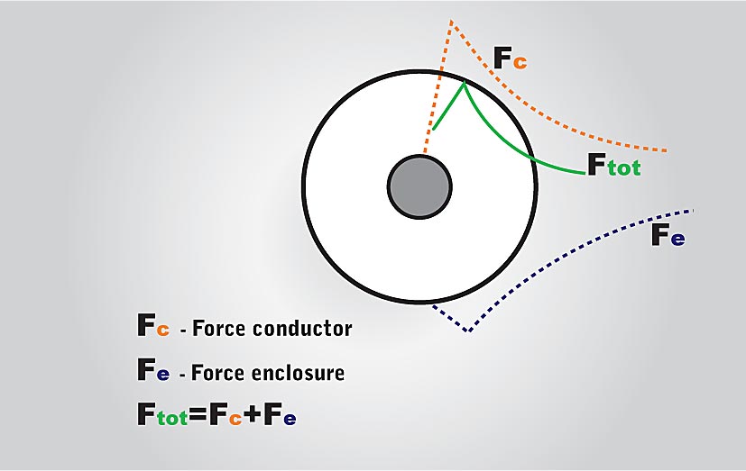
An additional result of the equal and opposite induction is found when a phase to ground condition arises. The mutual flux cancellation will eliminate the AC component of the short circuit forces. The force due to the short circuit DC component is reduced to a point where it can be easily contained by the insulating bus supports.
It is diagrammatically seen here that even the force produced by the DC component of the short circuit is somewhat off setting with their difference depending on the magnetic time constant of the IPB System.
With a Continuous IPB design, the enclosure also acts as a ground plane, eliminating the need for a separate ground bus. The enclosure is at ground potential over its entire length. Usually, a single connection to the station ground can provide complete grounding.
Additional material and installation savings are realized by eliminating the need for special insulated joints and hardware at the structural support points as required with non-continuous designs.
IPB's design construction makes internal single phase faults inherently rare.
Should a single phase fault occur in the connected equipment the IPB would usually not see the fault and its associated forces.
Phase to phase faults create the highest short circuit forces. Due to the inherent electrical isolation of the IPB conductors, the System has built in time constants which reduce the maximum forces produced in the faulted conductors to values less than half the maximum theoretically calculable non-time delayed forces.
The stresses on the conductors and insulators are greatly reduced to levels well below their safety design maximums.
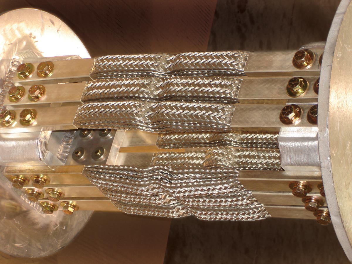
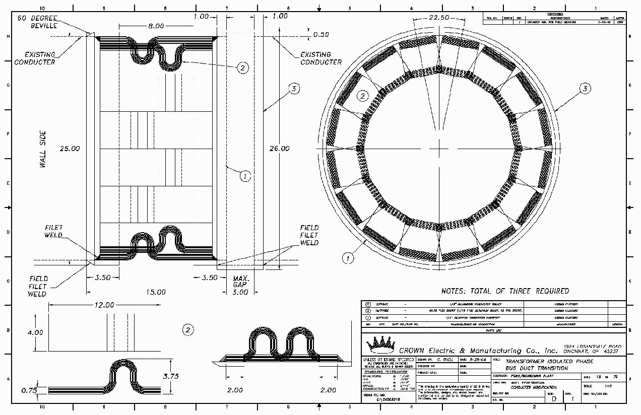
Flexible Braids
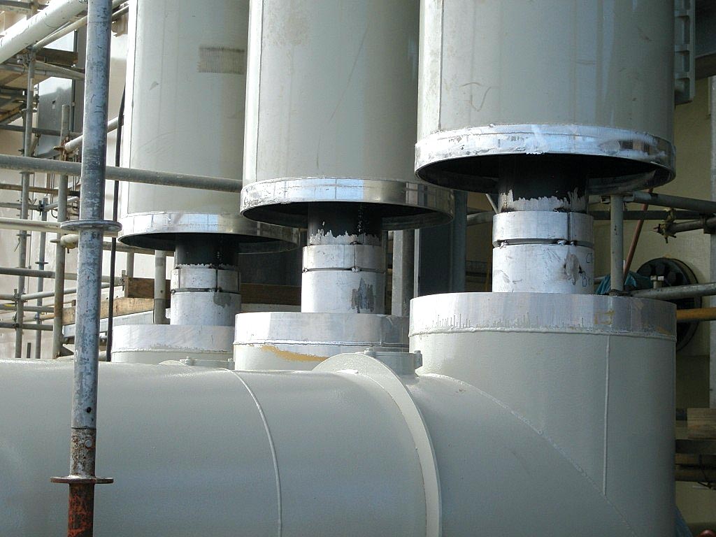
IPB connections to transformers, generators and breakers are made with flexible shunt braids. Flex braids provide three (3) axis adjustability, vibration nullification and act as removable isolation links.
Expansion
Thermal considerations are a crucial part of any IPB System design. IEEE and customer specifications determine the temperature limits over which the System may operate. Since the conductor and housing heat differently with each having different maximum thermal limits, each component must contend with the differing expansion of its companion component.
Crown Electric's IPB Insul-Mount system provides linear play for the conductor at each insulator brace point. The conductor's welded shunt design provides the additional buffering against linear expansion and contraction.
The IPB housings have custom rolled "bellows type" expansion rings that are perimeter welded to the end of an IPB section. These housing sections are then engineered to be inserted into the IPB run such that the expansion needs of the conductor and housing are co-linear.
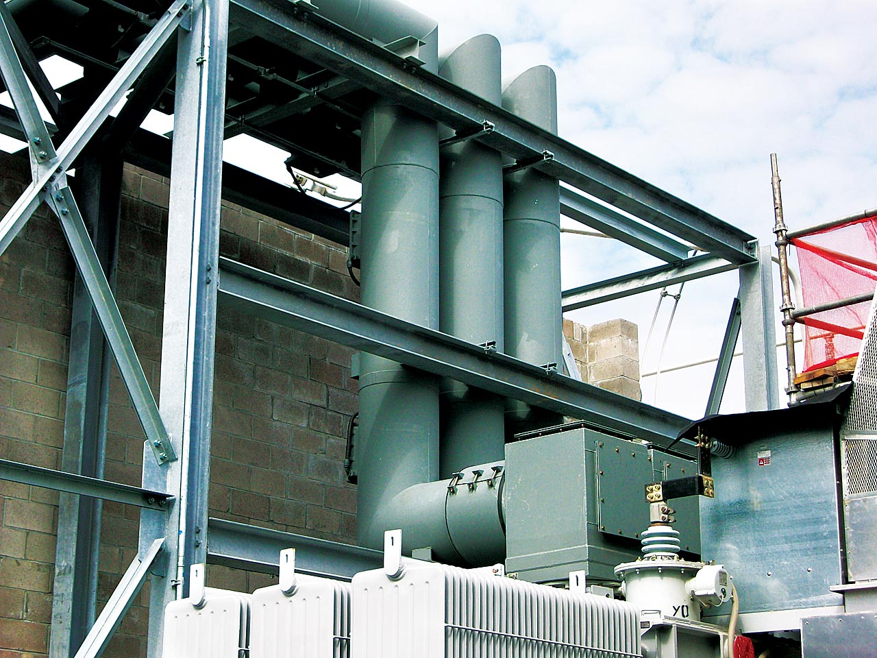
Crown Electric: Engineers – Designs – Fabricates and Installs IPB Cooling Packages for new - retrofit and upgrade applications.
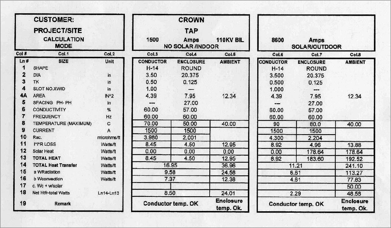
Forced Cooling (click)Once voltage clearances are accounted for, the physical size of Isolated Phase Bus housing and conductor is largely dictated by the system's continuous current rating and the maximum allowable temperature rise of the bus above the specified ambient temperature.
As the conductor current increases, it is necessary to dissipate the associated I2R heat loss generated to keep the bus within its allowable thermal rise. To limit the temperature rise to acceptable specified levels, it is necessary to either increase the physical size of the conductor and enclosure, or to actively dissipate the heat with some method of cooling.
Over the years, several methods of cooling have been investigated and under most circumstances the decidedly practical and economical method of actively dissipating the excess heat is the use of a closed forced air cooling system.
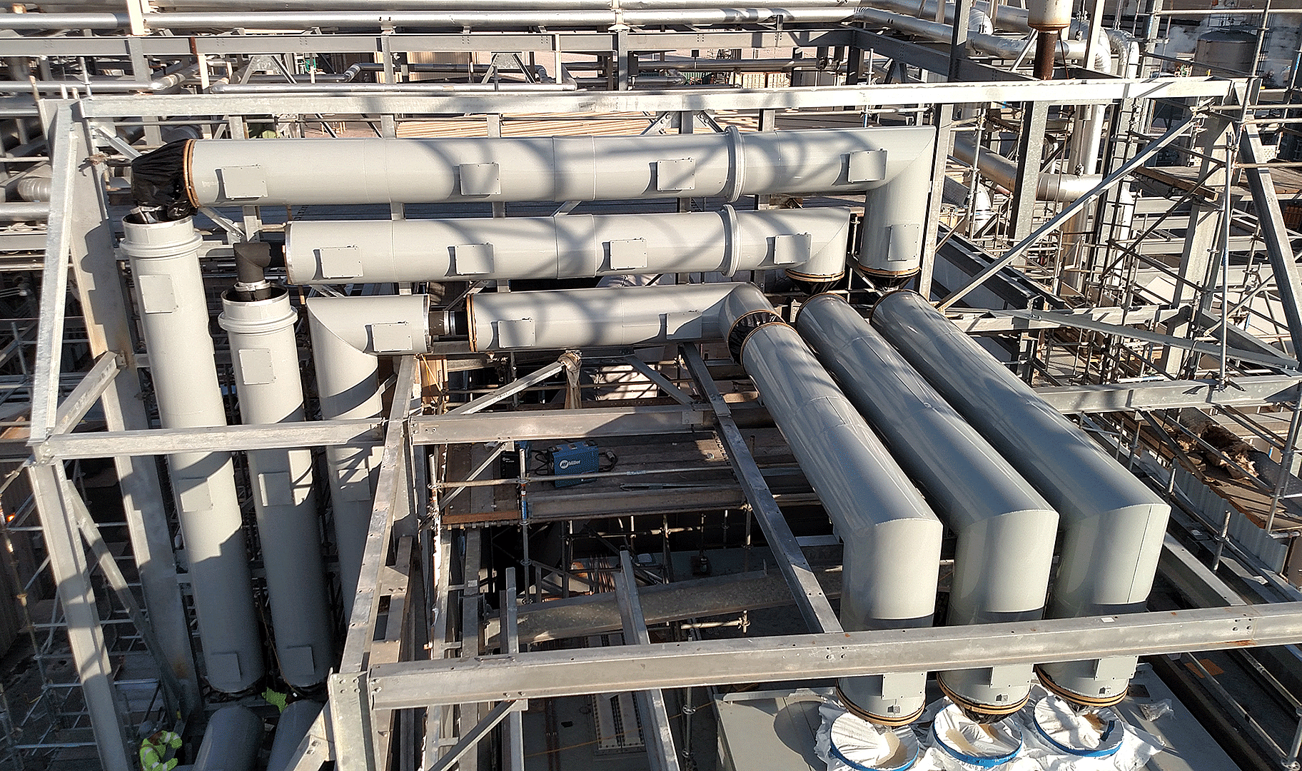
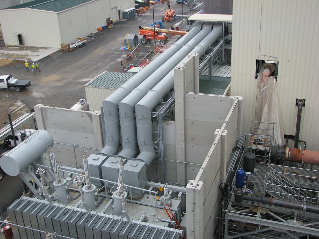
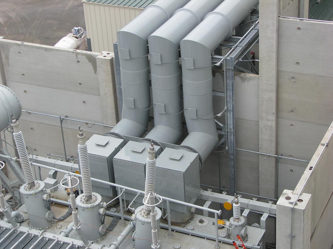
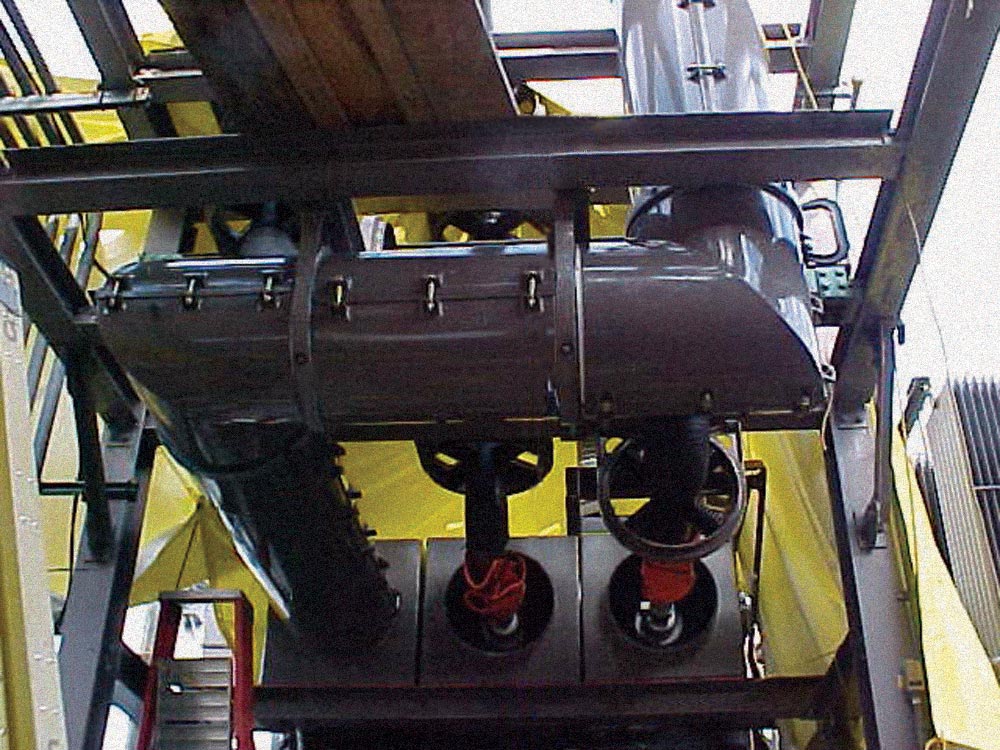
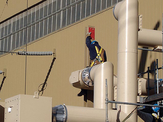
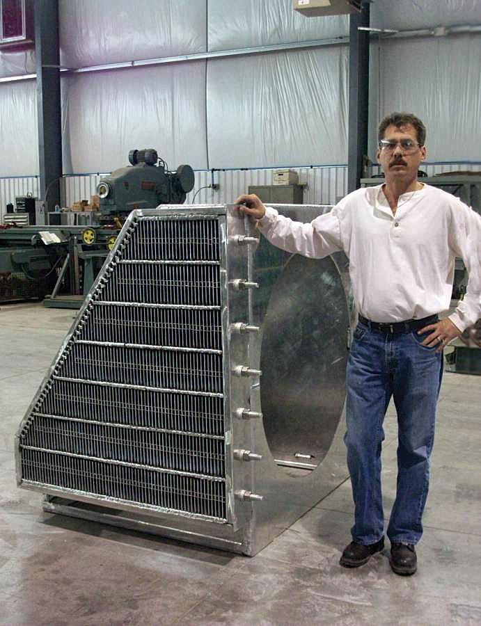
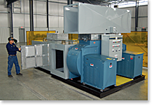
Forced Cooled System (click)
In a forced air system, air is channeled down the IPB housings in either the center or the outer two phases. Upon reaching the ends of the bus assembly, (at the generator and transformer ends), the air returns through the non-introduced phase(s). Except on very short bus runs, the heat exchanger is usually located as close as possible to the center of the linear bus run. The air flows from the heat exchanger towards both the transformer and generator. As the warm air flows out of the return phase(s) into the heat exchanger, it is dispersed by an equalizing baffle, then passed on to the cooling coils. The air then passes through a water eliminator before re-entering the enclosure(s) to be re-circulated.
Crown Electric's high efficiency, twin centrifugal fans feature in-line air flow. This arrangement provides either 50% or 100% backup cooling availability.
Monitoring, indication and alarm devices are available. The most common alarms indicate failure of air circulation in the bus and restrictions of water flow in the cooling coils.
In the event the forced air from one phase becomes ionized and then passes into another phase, the insulation integrity of the air between the conductor and the grounded enclosure can be reduced. This condition is alleviated by providing interphase de-ionizing baffles. The air plenums surrounding the de-ionizing baffles will often include regulators to adjust the air flow so that temperature balance can be managed due to unequal air paths and air velocities throughout the IPB system.
The retuning warm air flows out of the returning phase(s) and into the air to water heat exchanger where BTU's and moisture are removed and the process continues.
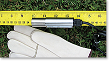
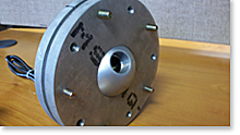
On-Line Thermal Monitoring of IPB (Joule-ious 105) (click)
Crown Electric optionally offers the Joule-ious 105 On Line thermal monitoring
system for both new and retrofit IPB applications.
The Joule-ious 105 is a ruggedized, high accuracy infrared touch-less thermal sensing system mounted on the IPB at points of connection to the major capital equipment (Generators and GSU's). The Joule-ious 105 continuously monitors, logs and reports the IPB temperature at each surveillance point. Multiple pre-alarms and alarms are fully programmable. Reporting and alarming can be local, remote, wired or wireless.
Now IPB Temperature Monitoring is easy and in your hands.
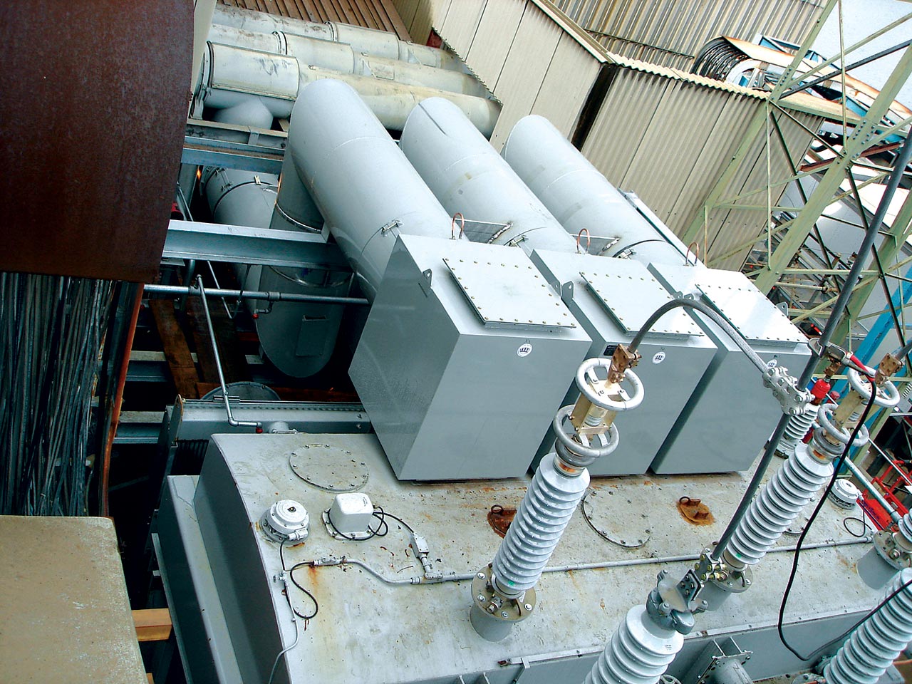
IPB Auxiliary Tap Bus
Maintaining the critical integrity of the IPB systems remains a priority for a number of lesser amperage auxiliary connections. These lower amperage connections may be part of the original system such as potential transformer taps or may be a newer system addition for upgrades such as Pollution Control Auxiliary Power requirements. Crown Electric maintains the same robust construction principles for all facets of the IPB system and can offer our current design improvements for legacy system upgrades, as well as new operational & functionality augmentations.
Potential Transformers
Potential transformer compartments employ draw-out construction with interlocking features to protect against hand touch access to the high voltage connection points in both the operating and withdrawn positions. The PT compartment front door is further interlocked so that it may not be un-latched without first electrically disconnecting the PT secondary circuitry. In the withdrawn position, the primary terminal of the potential transformer is automatically grounded.
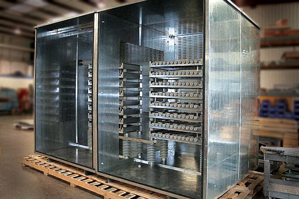
Neutral Grounding Equipment
Neutral grounding cubicles are generally constructed with angle iron frames and a channel base. The grounding transformer is enclosed by formed eleven (11) gauge steel with hinged doors for access and a solid barrier separating it from the resistor section. The resistors are shielded by expanded metal covers with removable screws. Interlocks are provided as specified.
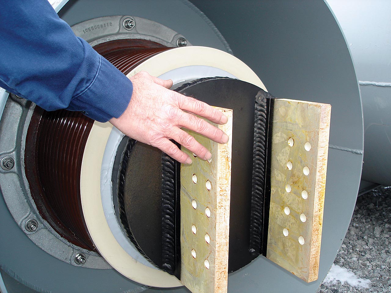
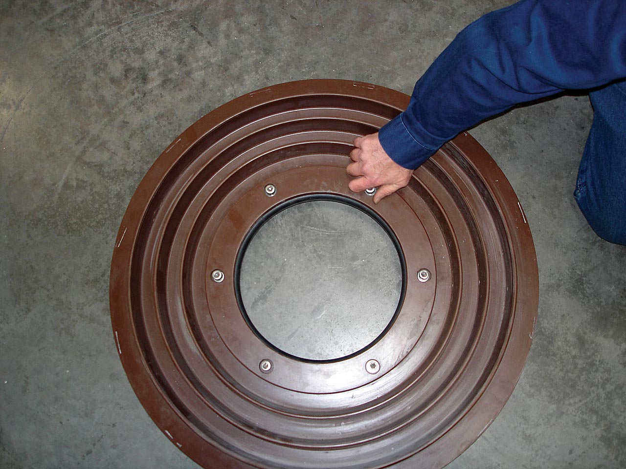
Hydrogen Seal
Hydrogen seals between the bus and generator bushings can be furnished when required. In the preferred design, an adapter is mounted on the generator bushing. A silicone diaphragm is mounted to the outer rim of the adapter and to the inside of the Isolated Phase Bus enclosure. The flexible shunts are bolted to the adapter and are within the force cooled bounds of the bus. The enclosure which contains the bushings is vented and will allow any free hydrogen to escape to the atmosphere.
The flexible silicone rubber diaphragm is molded with concentric ribs on both sides to produce a high creep distance. The flexible diaphragms place no stress on the bushing and exhibit excellent insulation characteristics as well as resistance to heat, tracking, ozone, oil, chemicals, etc.
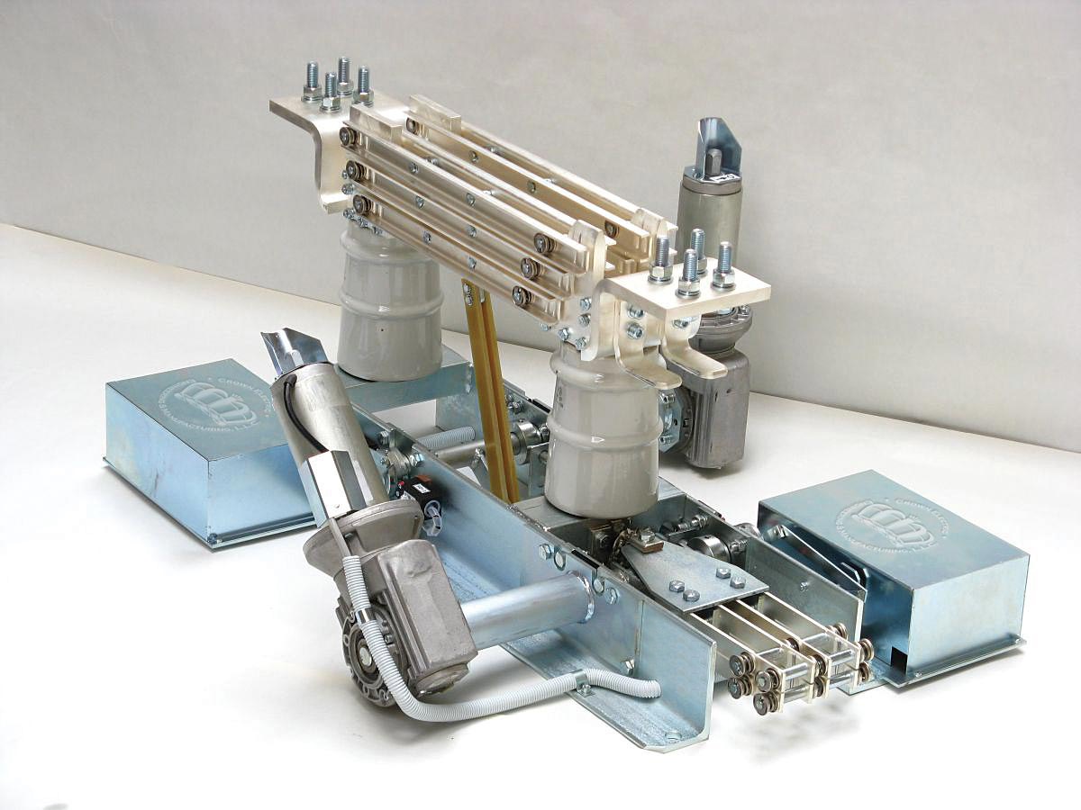
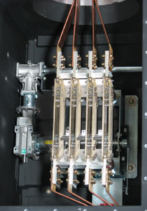
Disconnect Switches (watch video)
Isolated phase disconnect switches are optionally available for use in both IPB main runs and tap runs. Each disconnect switch pole is assembled in its own phase isolated compartment. The compartments are separated by air spaces to provide phase isolation equivalent to that of the IPB. The switches can be operated single phase or by a common gang operated mechanism which can be provided with mechanical and/or electrical position indicators and specified interlocking. Disconnect switch operating mechanisms can be specifed to be manually or electrically operated. Safety glass windows permit visual inspection of the switch contact position and allow for thermal scans.
Switches with ratings above 20,000 amps self-cooled have been supplied.
Current Transformers
Current transformers may be mounted directly in the low voltage bushing enclosures without increasing the outside diameter or reducing clearances. Secondary terminal boxes provide space for shorting terminal blocks and conduit connections for the secondary leads. An inspection hatch allows for monitoring or removal as may be required.
Space Heaters
Crown custom designed Insul-Mounttm insulator mounting castings provide the location and electrical connection points for customer specified IPB space heaters.
Solar Effects
Unless customer specifications differ, IPB design performance is in accordance with C 37.23 and based on "usual service conditions" as described therein. These designs will find "the effect of solar radiation not significant" as stated in C 37.23 Section 4c. When solar effects do become significant, Crown Electric designs rely additionally upon ANSI/IEEE C 37.24 "IEEE Guide for Evaluating the Effect of Solar Radiation on Outdoor Metal-Enclosed Switchgear" or appropriately exacting requirements as specified by the customer.
Crown Electric offers:
IPB Auditing, Benchmarking Reviews & Documentation Services for most
legacy IPB Systems.

Recent Updates:
Please click on images for a hi res version.

- Hover cursor over image to open witch
- Click for a promotional video